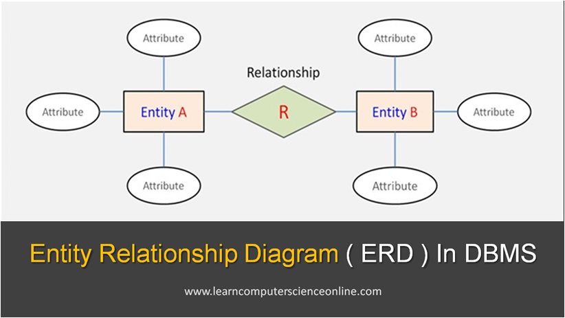
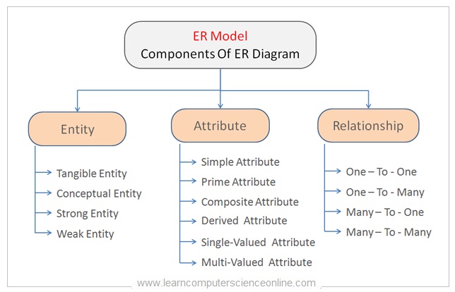
ER Diagram Component | ER Diagram Symbol |
Strong Entity |  |
Weak Entity |  |
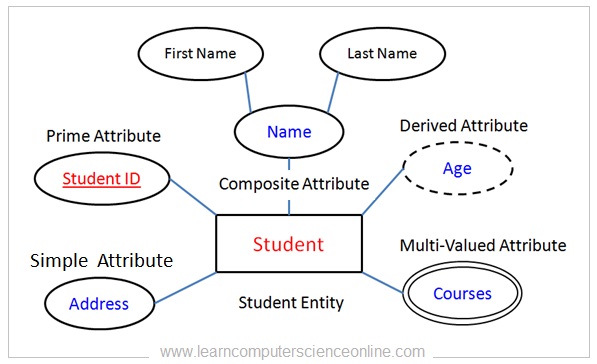
Simple Attribute |  |
Composite Attribute |  |
Derived Attribute |  |
Prime Attribute |  |
Multi-Valued Attribute |  |
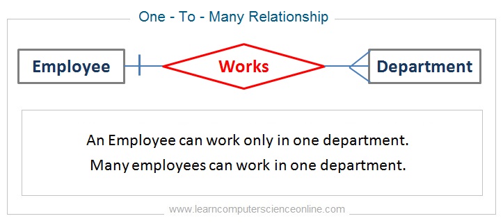
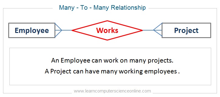
Relationship |  |
Weak Relationship |  |