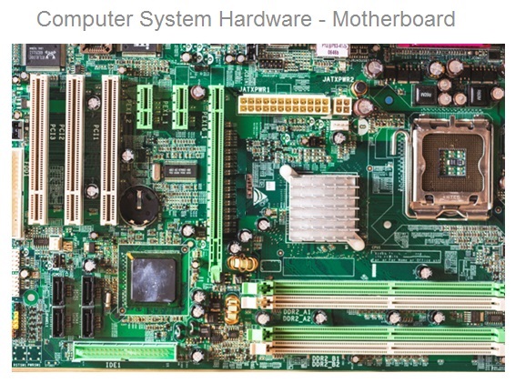
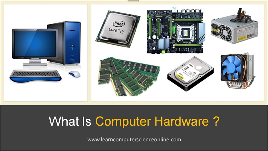
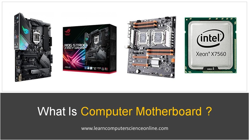
The motherboard is the main printed circuit board ( PCB ) which works as a connection junction for some of the most important components inside a computer system .
The motherboard ( PCB ) is a hardware component which defines the system configuration in terms of microprocessor and the main memory RAM supported by the PCB.
The computer motherboard is defined as an electronic circuit board which facilitates the connection between the central processing unit (CPU) , random access memory (RAM) , chipset, graphics card, sound card, hard disk and other electronic devices connected to the system.
In this article , you will learn what is motherboard , mother board parts and functions, how to connect motherboard, motherboard architecture , its types, form factor and how it is connected with other components such as RAM, CPU, hard disk, graphics card, network cards, power supply unit SMPS, expansion slots and other parts inside the computer system.
The computer system motherboard is the main printed circuit board of ( PCB ) where central processing unit ( CPU ) , RAM modules ( main system memory ) , disk memory ( hard disk ) and the peripheral devices are connected through chipset .
The mother board is an essential component of every computer system and it is fixed inside system case ( cabinet ) with the help of metallic screws .
The motherboard is a computer hardware and works as a circuit board for the connecting various system components , input and output devices.
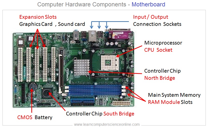
The mother board provides different types of expansion slots for adding the graphics card , sound card or any expansion card for additional functionality required in the system. It also provides the DIMM slots for adding the RAM modules.
The choice of mother board defines the system configuration in terms of processor socket ( Intel OR AMD processor ) , RAM module ( DDR1 , DDR2 , DDR3 and DDR4 ) that can be used .
Motherboard Types
What is Motherboard Form Factor ?
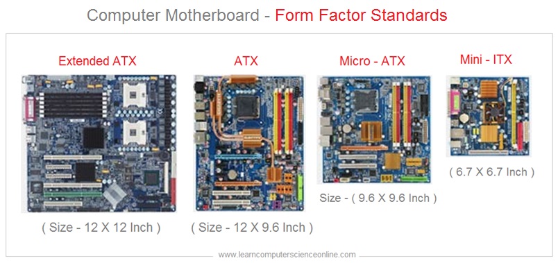
The computer mother boards ( PCB ) are manufactured in standard sizes and shapes called the form factor . The motherboard form factor defines the size of the motherboard in inches .
The motherboard form factor is referred to its size , shape , layout of the input and output ports panel and the mounting holes used for fixing the mother board into the system case .
The motherboard form factor is the uniform standard implemented by all the mother board manufacturing companies to ensure compatibility of various other hardware components.
The most commonly used form factor is ATX . The ATX motherboard is 12 X 9.6 inches , EATX which is an extended ATX is 12 X 12 inches , Micro ATX is 9.6 X 9.6 inch size ) and the Mini ITX comes in 6.7 X 6.7 inch size.
Motherboard Form Factor Standard
Motherboard Size
EATX
12 X 12 Inches
ATX
12 X 9.6 Inches
Micro ATX
9.6 X 9.6 Inches
Mini ITX
6.7 X 6.7 Inches
Motherboard Parts
What Are Types Of Motherboard Parts ?
Some of the most important hardware components are fitted on the motherboard. The mother board parts include :
The mother board provides may ports for connecting different types of input and output devices to the computer system . The processor ( CPU ) communicates with these devices through a controller chip .
The initial motherboard design had number of these controller chips scattered all across the mothered . This scattered chips on the motherboard used to give a very cluttered look to the motherboard design .
Due to advancement in motherboard architecture and the controller chip technology , later on, all these controller chips were merged into two large controller chips.
This design change was done to simplify the mother board architecture and to give a clean look.
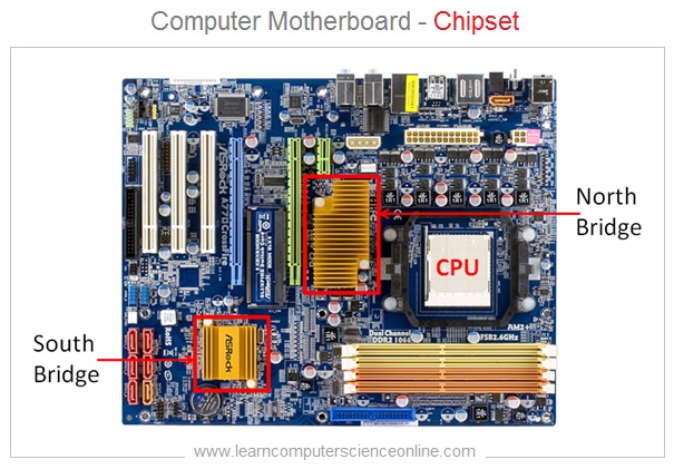
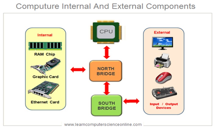
The mother board now comes with only two large controller chips called a chipset . The chip closest to the processor is called north bridge and other controller chip is called the south bridge .
This chipset works as a bridge and handles all the communication between the processor , main memory RAM , graphics card and various peripheral devices connected to the system .
The latest generation of mother boards are coming with only one controller chip and the north bridge chip is now integrated with the processor chip . However , the chipset mother board design is still very much in use .
What Is Chipset ?
North Bridge And South Bridge
The north bridge controller chip is closest to the processor and handles the communication with graphics card , sound card , network card , main memory RAM , disk memory .
Whereas , the south bridge works as a communication bridge between processor and various peripheral devices such as display monitor , keyboard , mouse and printer .
Important Changes
Latest Motherboard Chipset Architecture
The motherboard architecture has also evolved over a period . The MB design has significantly improved due to the advancement in the hardware technology.
In the latest generation of motherboard, the chipset is no longer split as two independent chips ( North And South bridge ). Rather, the MB now has only one single controller chip as chipset.
The newer range has only one single chip as south bridge and the north bridge ship is now integrated with the processor chip itself .
Motherboard CPU Sockets
LGA CPU Socket
PGA CPU Socket
BGA CPU Socket
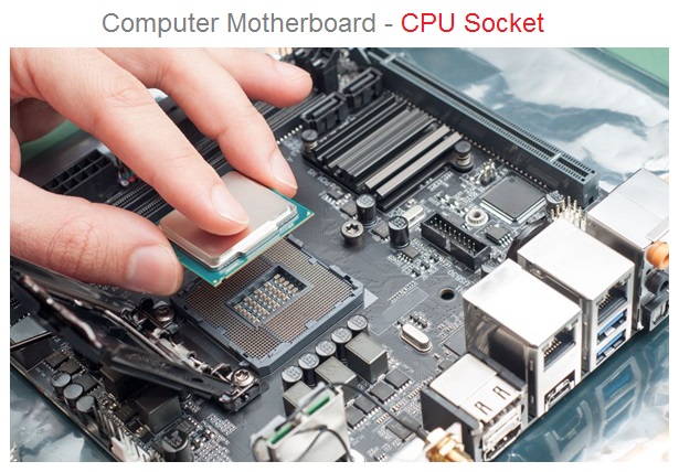
The microprocessor chip is installed into the processor socket available on the mother board . The most common type of mother board usually have only one CPU socket and only one processor chip can be installed on these mother boards .
However , the dual processor socket mother boards are now available in the market that comes with two CPU sockets which can accommodate two processor chips on the same mother board ( PCB ).
Each mother board supports a specific type of microprocessor ( CPU ) . The mother board socket can either support Intel processor or it will support AMD processor .
Both Intel And AMD processor chips have different base types ( Intel – LGA And AMD – PGA ) and therefore , it is important to first decide the processor brand ( Intel OR AMD ) before selecting the compatible mother board .
The CPU sockets have large number of pins which helps to distribute the power supply required by the CPU.
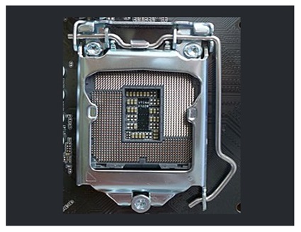
The CPU socket is also equipped with a retention arm which firmly holds the microprocessor chip into the CPU socket . This mechanism also protects the CPU from any damage due to any kind of pressure .
Each processor chip has a specific notch at one corner of the chip . This notch must match with the similar notch on the processor socket .
This notch along the edge of the processor chip ensures that only correct type of processor can be installed into the socket .
Types Of Motherboard CPU Sockets
There are three types of CPU sockets used on the mother board. In other words , the processor chip base comes in three types that fits into only compatible CPU socket .
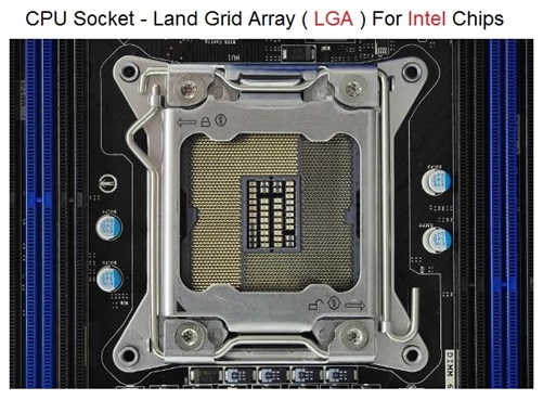
These three CPU socket types include LGA ( Land Grid Array ) , PGA ( Pin Grid Array ) and BGA ( Ball Grid Array ). But technically, BGA is not a CPU socket .
Land Grid Array ( LGA ) Socket
Pin Grid Array ( PGA ) Socket
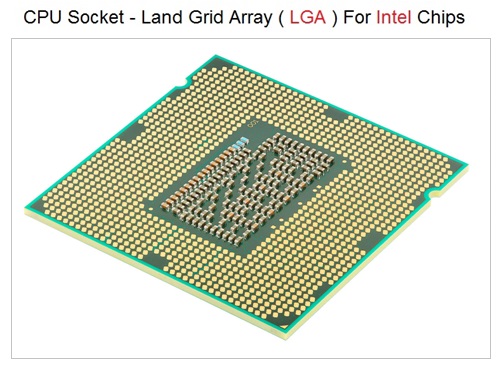
CPU Socket - Land Grid Array ( LGA )
The Intel processors come with LGA ( Land Grid Array ) base type and therefore , Intel processor does not have pins in the processor base . The Intel processor socket rather has pins which form contact with the processor chip when correctly installed into the socket.
The LGA type sockets ( Intel type ) are identified by the number of pins present in the CPU socket . For example, the LGA 1156 processor product code indicates the number of pins in the CPU socket and also the number of contact points present on the processor bottom .
Land Grid Array Socket
Land Grid Array Socket
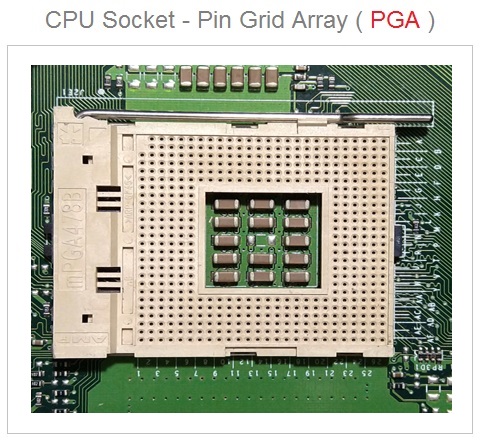
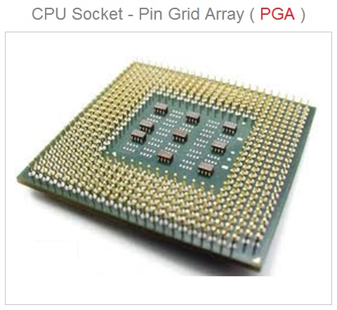
CPU Socket - Pin Grid Array ( PGA )
Whereas , the AMD processor comes with PGA ( Pin Grid Array ) type of base. The AMD processor chip have pins at the chip base that get inserted into the socket base when the AMD processor is correctly installed into the socket.
Pin Grid Array Socket
Pin Grid Array Socket
CPU Base Type - Ball Grid Array ( BGA )
The processor chips with BGA ( Ball Grid Array ) base are directly fitted on the motherboard without any CPU socket . So , technically the BGA is not a CPU socket .
These type of processors are mainly used in the mobile devices . The processor with BGA base are directly soldered on the PCB and therefore , cannot be easily replaced .
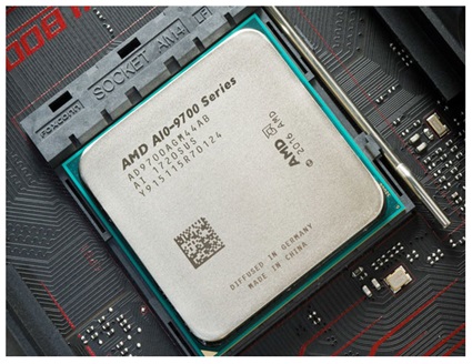
AM4 CPU Socket For AMD Processor
The AM4 socket is a CPU socket available on the AMD chip compatible mother boards used for installing the AMD Zen architecture series processor chips . The AM4 socket was first introduced in year 2016 to replace the previous versions AM3 and FM2 sockets .
The AMD processor with 1331 pins can be installed into the AM4 socket which has 1331 pin slots. The AM4 socket is the first from AMD to support DDR4 memory .
AM4 CPU Socket For AMD Processor
LGA 1151 CPU Socket For Intel Processor
LGA 1151 CPU Socket For Intel Processor
The LGA 1151 socket is a CPU socket available on the Intel chip compatible mother boards used for installing the Intel i3,i5 ,i7 series processor chips . The LGA 1151 socket is also called H4 Socket .
The LGA 1151 socket was introduced to replace the previous versions LGA 1150 ( Also called as H3 socket ) .
The Intel processor with 1151 pin slots can be installed into the LGA 1151 socket which has 1151 pins. The LGA 1151 socket can support DDR3 , DDR4 RAM memory modules.
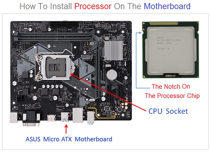
How To Install Microprocessor Chip On The Motherboard ?
The microprocessor chip is installed into the CPU socket on the mother board. It is important to follow the correct installation process to avoid any problem.
The motherboard and the microprocessor are delicate and expensive electronic components . And hence , due care must be observed during the installation of the processor chip into the CPU socket.
During the CPU installation , the processor chip must be held on the edges to avoid the finger contacts with processor pins . Similarly , the CPU socket inside cage should not be touched for any reason.
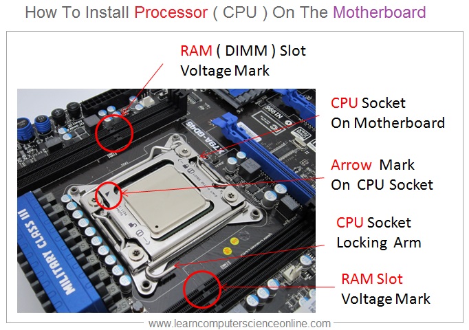
The processor chip and the CPU socket comes with either a notch or an arrow marked on the processor chip and also on the CPU socket .
The processor chip must be oriented and placed properly with the help of this a notch or an arrow so that it is correctly installed into the CPU socket on the mother board.
The processor socket has a cover that can opened and closed with the help of a mechanical handle provided on the CPU socket .This mechanical locking mechanism firmly holds the processor chip into the CPU socket.
CAUTION
The processor chip compatibility with the CPU socket on the mother board can be verified by refereeing to the motherboard manual .
If the wrong processor chip is installed or if the CPU is not oriented correctly into the processor socket may cause damage to either the processor chip or CPU socket or both .
Please read the mother board manual and processor manual to ensure processor compatibility with the CPU socket on the mother board.
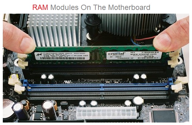
RAM Installation
How To Install RAM Modules On The Motherboard DIMM Slots ?
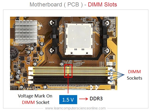
The main memory RAM modules are installed into the DIMM Slots available on the mother board. The correct type of RAM modules can only be installed into the DIMM slots supported by the motherboard . This depends on the mother board architecture.
The DIMM stands for Duel In-Line Memory Module.
The number of RAM modules that can be installed on the motherboard depends upon the number of DIMM slots present on the mother board.
And the number of DIMM slots available depends on the mother board type ( Form Factor – ATX , Mini ATX , Micro ITX ).
The RAM modules compatibility in terms RAM module type ( DDR2 , DDR3 and DDR4 ) , its frequency , voltage and channels supported must be verified . This information can be easily obtained from the motherboard manual .
Each RAM module has a notch which perfectly matches with the similar notch on the DIMM slot . The RAM slot on the mother board also mentions the RAM module voltage supported by the slot.
The RAM modules are installed into the DIMM slots present on the motherboard . The number of DIMM slots depends upon the mother board Form Factor . But usually these DIMM slots ranges anywhere between two to eight slots.
The RAM compatible specifications and the type of the RAM module that cab fitted is usually mention on the PCB ( Motherboard Printed Circuit Board ) .
In case if this information is missing on the PCB then the PCB ( Mother board ) manual provides this information.
The voltage for the RAM module is also printed in the middle of the each DIMM socket. This voltage value indicates the suitable DDR version ( DDR 1, 2, 3, 4 ) of the RAM module that can installed and supported by the DIMM socket.
Motherboard DIMM Slots
RAM Module Standards
RAM Standard
Voltage
Frequency MHz
SDRAM
3.3 Volts
100 - 166 MHz
DDR1
2.5 To 2.6 Volts
266 - 400 MHz
DDR2
1.8 Volts
533 - 800 MHz
DDR3
1.35 To 1.5 Volts
1066 - 1866 MHz
DDR4
1.2 Volts
2136 - 3600 MHz
What is Motherboard ?
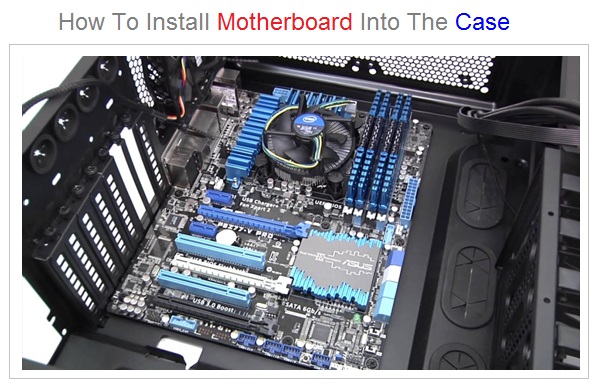
How To Install Motherboard ?
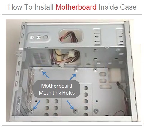
The mother board ( PCB ) is installed into the system case ( cabinet ) . The PCB is fitted inside the system case unit by using special screws provided along with the case .
These special screws provide the necessary ground clearance and firmly hold the PCB into the system case . The mother board is always fixed slightly elevated and PCB bottom should not touch the case.
Some system case unit has elevated mother board mounting screw holes inside the system case as visible in this case image . And MB PCB can fixed using any suitable screws.
How To Install Motherboard ?
How To Install Motherboard ?
IMPORTANT
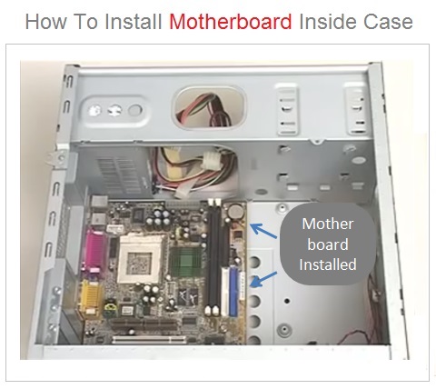
While assembling a new PC , It is a good practice to first install the processor chip into the CPU socket , CPU heat sink and the RAM modules into the DIMM sockets .
Further , it is highly recommended to first test run the system by connecting other components such as SMPS power unit , hard disk , keyboard and display monitor before fixing the mother board into the case.
This is just to ensure that all vital system components are working fine and the system is ready for final assembly. After successful test run , the mother board can fixed into the case.
What is Motherboard ?
BIOS And CMOS
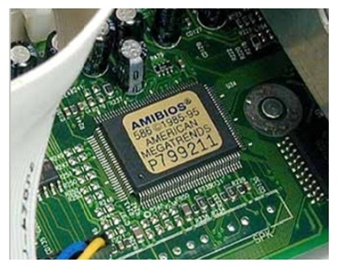
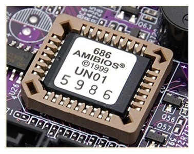
The BIOS stands for Basic Input Output System. The BIOS is a type of system software placed in a ROM chip . And therefore, it is also called as ROM BIOS.
The BIOS chip is present on the mother board along with CMOSBattery . The CMOS stands for Complementary Metal oxide Semiconductor.
BIOS Chip On MB
BIOS Chip On MB
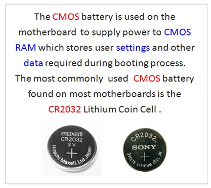
CMOS Battery
The CMOS is battery powered small memory chip present on the MB. The CMOS memory chip stores the user settings and other data used by the BIOS for initializing the hardware during the booting process.
The average life of the CMOS battery is five years. When the system fails to retain the current data and time, the CMOS battery needs to be replaced.
The BIOS is the first start-up program executed by the central processing unit ( CPU ) whenever the computer system is switched on.
COMS Battery On MB
CMOS Battery On MB
BIOS Functions
The main function of the BIOS program is to perform the POST and hardware check , initialize the hardware and then load the main operating system into the main memory RAM .
The BIOS then handover the control to the operating system when it is loaded into the memory and fully operational.
The system initiates the booting sequence first by performing the POST . The POST stands for power on self test . If POST is successful , the BIOS then loads the initial set of drivers.
The booting process ends when the main operating system is loaded and the system is ready for other applications to run.
Where Is BIOS Chip ?
As the mother board architecture evolved , the BIOS chip design and its placement on the MB has also changed.
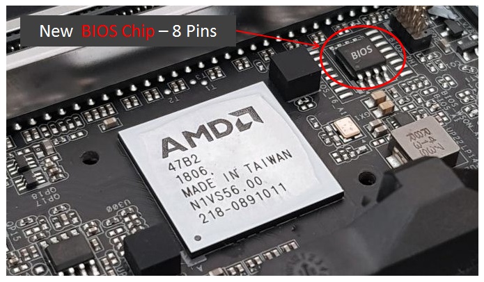
The BIOS chip size in terms of number of pins on the BIOS chip has progressively declined. The older BIOS used to have either 32 or 30 pins into the BIOS chip.
However , the current generation BIOS chips very small wit only 8 pins. Most mother board brands keep the BIOS chip closer to the CPU socket.
New BIOS Chip - 8 Pins
Where Is CMOS Chip ?
The CMOS chip used to be prominently visible in the form of RTC chip on the older design motherboard.
However , as the mother board architecture evolved , the CMOS chip design and its placement on the MB has also changed.
The CMOS chip is no longer visible on the mother board because it now merged and integrated into the north bridge chipset.
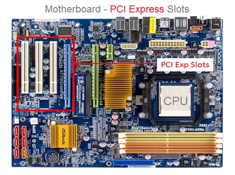
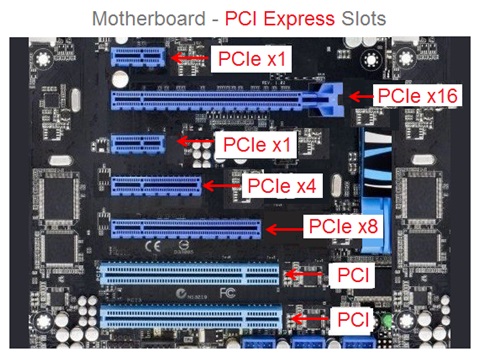
What Are Motherboard PCI Slots ?
Expansion Slots
Expansion Cards
Sometimes it becomes necessary to enhance the system features and performance by adding an additional piece of hardware called expansion card.
Different types of expansion card are used such as graphics card , sound card or a network card as per system requirements.
These cards are installed on the motherboard into the PCI slots. Different types of PCI slots are used for various expansion cards.
These expansion slots are the connection ports present on all mother boards where expansion card can be inserted to add additional features and functionality to the computer system .
For example, you may wish to upgrade your system into a high end gaming computer by adding a graphics card to enhance the gaming experience.
PCI Slots On MB
Types Of PCI Slots
The PCI express slots are the most commonly used expansion slots. The PCIe stands for PCI Express. The PCI Express is a new technology that has replaced the AGP slots.
The mother board usually has different types PCI express slots with different data transfer speed . For example the PCI Express x16 slots can transfer the data at 4GBs per second.
The PCI Express slots come in five different sizes and speeds which include PCIe x1, PCIe x2, PCIe x4, PCIe x8, and PCIe x16.
The PCIe x16 slots are best suited for the graphics cards. The number indicates the PCI express lanes available in the slots.
This is the most comprehensive and unique Computer Science And Programming Fundamentalscourse Online which will give you in depth understanding of most important fundamental concepts in computer science And Programming .